platformio configuration file

platformio.ini (configuration file)

Each PlatformIO project has a configuration file named platformio.ini in the root directory for the project.
platformio.ini has sections (each denoted by a [header]) and key / value pairs within the sections. Lines beginning with ; are ignored and may be used to provide comments.
Multiple value options can be specified in two ways:

  1. Split values with “, ” (comma + space)
  2. Multi-line format, where each new line starts with at least two spaces

there are two main sections
1- PlatformIO Core (CLI) settings: Section [platformio]
2- Environment settings: Section [env]

[platformio]

description : Short description of the project

default_envs : The platformio run command processes all environments [env:***] by default if the platformio run --environment option is not specified. 

extra_configs : This option allows extending a base “platformio.ini” (Project Configuration File) with extra configuration files.

Base “platformio.ini”

[platformio]
description = this is new project 
default_envs = esp32dev
extra_configs =
  extra_envs.ini
  extra_debug.ini

; Global data for all [env:***]
[env]
platform = espressif32
framework = espidf

; Custom data group
; can be use in [env:***] via ${common.***}
[common]
debug_flags = -D RELEASE
lib_flags = -lc -lm

[env:esp-wrover-kit]
board = esp-wrover-kit
build_flags = ${common.debug_flags}

extra_envs.ini

[env:esp32dev]
board = esp32dev
build_flags = ${common.lib_flags} ${common.debug_flags}

[env:lolin32]
platform = espressif32
framework = espidf
board = lolin32
build_flags = ${common.debug_flags}

src_dir: The path to the project’s directory with source code. Default: “Project/src
lib_dir : You can put your own/private libraries here. The source code of each library should be placed in a separate directory Default: “Project/data

For example, see how the Foo and Bar libraries are organized:

|--lib
|  |--Bar
|  |  |--docs
|  |  |--examples
|  |  |--src
|  |     |- Bar.c
|  |     |- Bar.h
|  |--Foo
|  |  |- Foo.c
|  |  |- Foo.h
|- platformio.ini
|--src
   |- main.c

Then in src/main.c you should use:

#include <Foo.h>
#include <Bar.h>

[env]

Each project may have multiple configuration environments defining the available project tasks for building, programming, debugging, unit testing, device monitoring, library dependencies, etc.

Common [env] : An optional configuration environment with common options that will be shared between all [env:NAME] environments in the platform.ini file.
example:

[env]
platform = ststm32
framework = stm32cube
board = nucleo_l152re
lib_deps = Dep1, Dep2

[env:release]
build_flags = -D RELEASE
lib_deps =
    ${env.lib_deps}
    Dep3

[env:debug]
build_type = debug
build_flags = -D DEBUG
lib_deps = DepCustom

Environment [env:NAME] : A section with an env: prefix defines a working environment for platformio runplatformio testplatformio checkplatformio debug and other commands. Multiple [env:NAME] environments with different NAME are allowed. Every project must define at least one working environment.
Each environment must have a unique NAME. The valid chars for NAME are letters a-z, numbers 0-9, special char _ (underscore). For example, [env:hello_world].

you can use options inside [env] the next link for all available options
https://docs.platformio.org/en/latest/projectconf/section_env.html#options

Dynamic variables

Dynamic variables (interpolations) are useful when you have a custom configuration data between build environments. For examples, extra build_flags or project dependencies lib_deps.

Each variable should have a next format: ${<section>.<option>}, where <section> is a value from [<section>] group, and <option> is a first item from pair <option> = value.

You can inject system environment variable using sysenv as a section. For example, ${sysenv.HOME}.

  • Variable can be applied only for the option’s value
  • Multiple variables are allowed
  • The Section [platformio] and Section [env] sections are reserved and could not be used as a custom section. Some good section names might be extra or custom.
[env]
; Unix
lib_extra_dirs = ${sysenv.HOME}/Documents/Arduino/libraries
; Windows
lib_extra_dirs = ${sysenv.HOMEDRIVE}${sysenv.HOMEPATH}\Documents\Arduino\libraries

; You MUST inject these options into [env:] section
; using ${extra.***} (see below)
[extra]
build_flags = -D VERSION=1.2.3 -D DEBUG=1
lib_deps_builtin =
  SPI
  Wire
lib_deps_external = ArduinoJson@>5.6.0

[env:uno]
platform = atmelavr
framework = arduino
board = uno
build_flags = ${extra.build_flags}
lib_deps =
  ${extra.lib_deps_builtin}
  ${extra.lib_deps_external}

[env:nodemcuv2]
platform = espressif8266
framework = arduino
board = nodemcuv2
build_flags = ${extra.build_flags} -Wall
lib_deps =
  ${extra.lib_deps_builtin}
  ${extra.lib_deps_external}
  PubSubClient@2.6
  OneWire

; Keep sensitive data in environment variables
;
; Unix
; export WIFI_SSID='\"my\ ssid\ name\"'
; export WIFI_PASS='\"my\ password\"'
;
; Windows
; set WIFI_SSID='"my ssid name"'
; set WIFI_PASS='"my password"'

[env:esp32dev]
extends = env:nodemcuv2
platform = espressif32
board = esp32dev
build_flags =
  -DWIFI_SSID=${sysenv.WIFI_SSID}
  -DWIFI_PASS=${sysenv.WIFI_PASS}

Differences between Synchronous and Nonsynchronous Rectifying DC/DC Conversion

The nonsynchronous rectifying type, which has been in use for years, features a simple circuit for a switching regulator, with an efficiency barely topping 80%. Subsequently, the appearance of battery-powered applications drawing relatively large power and requiring high efficiency, such as notebook PCs, has led to the development of a succession of ICs for synchronous rectifying switching regulators capable of delivering superior efficiency. Aided by innovations that have facilitated the design of the synchronous rectifying type requiring complex control and circuitry, this type of switching regulator, offering a maximum efficiency close to 95%, has gradually become predominant.

ESP32 ADC and DAC

ADC

ADC is Non-linear Ideally, you would expect a linear behavior when using the ESP32 ADC pins. However, that doesn’t happen. What you’ll get is behavior as shown in the following chart:

typical inputs are VP or VN or others 16 pins so The ESP32 supports measurements in 18 different channels
The voltage measured is then assigned to a value between 0 and 4095(12 bits), in which 0 V corresponds to 0, and 3.3 V corresponds to 4095. Any voltage between 0 V and 3.3 V will be given the corresponding value in between.

the easiest way to use adc is

analogRead(GPIO);
analogReadResolution(resolution)//set the sample bits and resolution. It can be a value between 9 (0 – 511) and 12 bits (0 – 4095). Default is 12-bit resolution.

but actually there are other useful functions

analogSetWidth(width): set the sample bits and resolution. It can be a value between 9 (0 – 511) and 12 bits (0 – 4095). Default is 12-bit resolution.
analogSetCycles(cycles): set the number of cycles per sample. Default is 8. Range: 1 to 255.
analogSetSamples(samples): set the number of samples in the range. Default is 1 sample. It has an effect of increasing sensitivity.
analogSetClockDiv(attenuation): set the divider for the ADC clock. Default is 1. Range: 1 to 255.
analogSetAttenuation(attenuation): sets the input attenuation for all ADC pins. Default is ADC_11db. Accepted values:
ADC_0db: sets no attenuation (1V input = ADC reading of 1088).
ADC_2_5db: sets an attenuation of 1.34 (1V input = ADC reading of 2086).
ADC_6db: sets an attenuation of 1.5 (1V input = ADC reading of 2975).
ADC_11db: sets an attenuation of 3.6 (1V input = ADC reading of 3959).
analogSetPinAttenuation(pin, attenuation): sets the input attenuation for the specified pin. The default is ADC_11db. Attenuation values are the same from previous function.
adcAttachPin(pin): Attach a pin to ADC (also clears any other analog mode that could be on). Returns TRUE or FALSE result.
adcStart(pin), adcBusy(pin) and adcEnd(pin): starts an ADC convertion on attached pin’s bus. Check if conversion on the pin’s ADC bus is currently running (returns TRUE or FALSE). Get the result of the conversion: returns 16-bit integer.

DAC

there are two DAC GPIO in esp32 GPIO25 and GPIO26

#define DAC1 25
 
void setup() {
  Serial.begin(115200);
  
}
 
void loop() { // Generate a Sine wave
  int Value = 255; //255= 3.3V 128=1.65V
  
  dacWrite(DAC1, Value);
  delay(1000);
}

ESP32 Developing Board

power delivery circuit

power coming from terminals or from usb
1- in the terminal we use diode D3 to reverse polarity protection before it going to the voltage regulator
2- at the same time the power coming from USB it connected with SP0503 IC it used for ESD protection (figure 3)

figure 3

3- 5v from the termianals or USB going to voltage regulator Vin to get 3.3v in Vout.

USB to UART and auto program circuits

CP2102

1- VBUS connected directly with USB Vcc
2-D+ and D- connected with D+ and D- with USB
3-GND connected with USB GND

in ESP32 once you pull IO0 and EN down you will get this message

rst:0x1 (POWERON_RESET),boot:0x3 (DOWNLOAD_BOOT(UART0/UART1/SDIO_REI_REO_V2))
waiting for download
ets Jun 8 2016 00:22:57

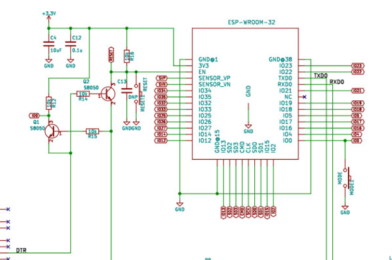
cp2102 and ch340g have DTR(Data Terminate Ready) and RTS(Request To Send) it used like handshake between cp2102 and ESP
once RTS become high and DTR low the GPIO0 pull to low and when DTR become high and RTS low EN pull to low

UART Protocol

How UART Works?

In UART Serial Communication, the data is transmitted asynchronously i.e. there is no clock or other timing signal involved between the sender and receiver. Instead of clock signal, UART uses some special bits called Start and Stop bits.

These bits are added to the actual data packet at the beginning and end respectively. These additional bits allows the receiving UART to identify the actual data.

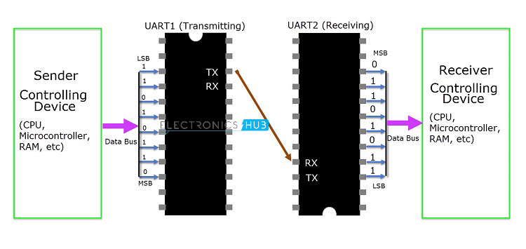
The image above shows a typical UART connection. The transmitting UART receives data from the controlling device through the data bus. The controlling device can be anything like a CPU of a microprocessor or a microcontroller, memory unit like a RAM or ROM, etc. The data received by the transmitting UART from the data bus is parallel data.

To this data, the UART adds Start, Parity and Stop bits in order to convert it into a data packet. The data packet is then converted from parallel to serial with the help of shift register and is transmitted bit – by – bit from the TX pin.

The receiving UART receives this serial data at the RX pin and detects the actual data by identifying the start and stop bits. Parity bit is used to check the integrity of the data.

Up on separating the start, parity and stop bits from the data packet, the data is converted to parallel data with the help of shift register. This parallel data is sent to the controller at the receiving end through a data bus.

Structure of Data Packet or Frame

The data in UART serial communication is organised in to blocks called Packets or Frames. The structure of a typical UART Data Packet or the standard framing of the data is shown in the following image.

Let us see about each piece of the frame.

Start Bit: Start bit is a synchronisation bit that is added before the actual data. Start bit marks the beginning of the data packet. Usually, an idle data line i.e. when the data transmission line is not transmitting any data, it is held at a high voltage level (1).

In order to start the data transfer, the transmitting UART pulls the data line from high voltage level to low voltage level (from 1 to 0). The receiving UART detects this change from high to low on the data line and begins reading the actual data. Usually, there is only one start bit.

Stop Bit: The Stop Bit, as the name suggests, marks the end of the data packet. It is usually two bits long but often only on bit is used. In order to end the transmission, the UART maintains the data line at high voltage (1).

Parity Bit: Parity allows the receiver to check whether the received data is correct or not. Parity is a low – level error checking system and comes in two varieties: Even Parity and Odd Parity. Parity bit is optional and it is actually not that widely used.

Data Bits: Data bits are the actual data being transmitted from sender to receiver. The length of the data frame can be anywhere between 5 and 9 (9 bits if parity is not used and only 8 bits if parity is used). Usually, the LSB is the first bit of data to be transmitted (unless otherwise specified).

Rules of UART

As mentioned earlier, there is no clock signal in UART and the transmitter and receiver must agree on some rules of serial communication for error free transfer of data. The rules include:

  • Synchronisation Bits (Start and Stop bits)
  • Parity Bit
  • Data Bits and
  • Baud Rate

We have seen about synchronisation bits, parity bit and data bits. Another important parameter is the Baud Rate.

Baud Rate: The speed at which the data is transmitted is mentioned using Baud Rate. Both the transmitting UART and Receiving UART must agree on the Baud Rate for a successful data transmission.

Baud Rate is measured in bits per second. Some of the standard baud rates are 4800 bps, 9600 bps, 19200 bps, 115200 bps etc. Out of these 9600 bps baud rate is the most commonly used one.

Let us see an example data frame where two blocks of data i.e. 00101101 and 11010011 must be transmitted. The format of the frame is 9600 8N1 i.e. 9600 bps with 8 bits of data, no parity and 1 stop bit. In this example, we haven’t used the parity bit.


Advantages of UART

  • Requires only two wires for full duplex data transmission (apart from the power lines).
  • No need for clock or any other timing signal.
  • Parity bit ensures basic error checking is integrated in to the data packet frame.

Disadvantages of UART

  • Size of the data in the frame is limited.
  • Speed for data transfer is less compared to parallel communication.
  • Transmitter and receiver must agree to the rules of transmission and appropriate baud rate must be selected.