
ADC
ADC is Non-linear Ideally, you would expect a linear behavior when using the ESP32 ADC pins. However, that doesn’t happen. What you’ll get is behavior as shown in the following chart:

typical inputs are VP or VN or others 16 pins so The ESP32 supports measurements in 18 different channels
The voltage measured is then assigned to a value between 0 and 4095(12 bits), in which 0 V corresponds to 0, and 3.3 V corresponds to 4095. Any voltage between 0 V and 3.3 V will be given the corresponding value in between.
the easiest way to use adc is
analogRead(GPIO);
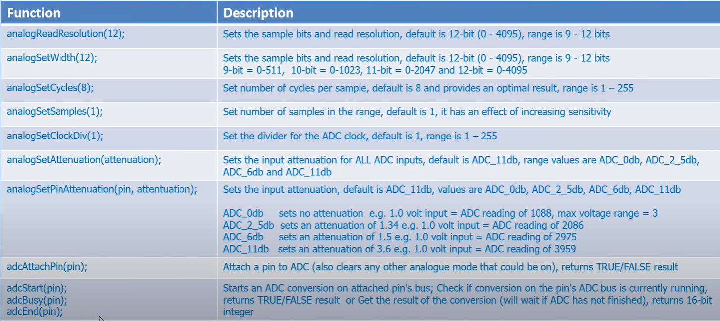
analogReadResolution(resolution)//set the sample bits and resolution. It can be a value between 9 (0 – 511) and 12 bits (0 – 4095). Default is 12-bit resolution.but actually there are other useful functions
analogSetWidth(width): set the sample bits and resolution. It can be a value between 9 (0 – 511) and 12 bits (0 – 4095). Default is 12-bit resolution.
analogSetCycles(cycles): set the number of cycles per sample. Default is 8. Range: 1 to 255.
analogSetSamples(samples): set the number of samples in the range. Default is 1 sample. It has an effect of increasing sensitivity.
analogSetClockDiv(attenuation): set the divider for the ADC clock. Default is 1. Range: 1 to 255.
analogSetAttenuation(attenuation): sets the input attenuation for all ADC pins. Default is ADC_11db. Accepted values:
ADC_0db: sets no attenuation (1V input = ADC reading of 1088).
ADC_2_5db: sets an attenuation of 1.34 (1V input = ADC reading of 2086).
ADC_6db: sets an attenuation of 1.5 (1V input = ADC reading of 2975).
ADC_11db: sets an attenuation of 3.6 (1V input = ADC reading of 3959).
analogSetPinAttenuation(pin, attenuation): sets the input attenuation for the specified pin. The default is ADC_11db. Attenuation values are the same from previous function.
adcAttachPin(pin): Attach a pin to ADC (also clears any other analog mode that could be on). Returns TRUE or FALSE result.
adcStart(pin), adcBusy(pin) and adcEnd(pin): starts an ADC convertion on attached pin’s bus. Check if conversion on the pin’s ADC bus is currently running (returns TRUE or FALSE). Get the result of the conversion: returns 16-bit integer.


DAC
there are two DAC GPIO in esp32 GPIO25 and GPIO26
#define DAC1 25

void setup() {
  Serial.begin(115200);

}

void loop() { // Generate a Sine wave
  int Value = 255; //255= 3.3V 128=1.65V

  dacWrite(DAC1, Value);
  delay(1000);
}