Inverting
Amplifiers or any operational amplifier for that matter and these are.
- No Current Flows into the Input Terminals
- The Differential Input Voltage is Zero as V1 = V2 = 0 (Virtual Earth)
Then by using these two rules we can derive the equation for calculating the closed-loop gain of an inverting amplifier, using first principles.
Current ( i ) flows through the resistor network as shown.


Then, the Closed-Loop Voltage Gain of an Inverting Amplifier is given as.

and this can be transposed to give Vout as:

Non-inverting

In the previous Inverting Amplifier tutorial, we said that for an ideal op-amp “No current flows into the input terminal” of the amplifier and that “V1 always equals V2”. This was because the junction of the input and feedback signal ( V1 ) are at the same potential.
In other words the junction is a “virtual earth” summing point. Because of this virtual earth node the resistors, Rƒ and R2 form a simple potential divider network across the non-inverting amplifier with the voltage gain of the circuit being determined by the ratios of R2 and Rƒ as shown below.
Equivalent Potential Divider Network

Then using the formula to calculate the output voltage of a potential divider network, we can calculate the closed-loop voltage gain ( AV ) of the Non-inverting Amplifier as follows:

Then the closed loop voltage gain of a Non-inverting Operational Amplifier will be given as:

Summing

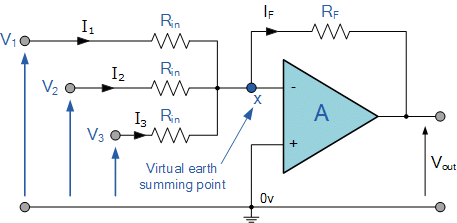
In this simple summing amplifier circuit, the output voltage, ( Vout ) now becomes proportional to the sum of the input voltages, V1, V2, V3, etc. Then we can modify the original equation for the inverting amplifier to take account of these new inputs thus:

However, if all the input impedances, ( RIN ) are equal in value, we can simplify the above equation to give an output voltage of:
Summing Amplifier Equation

Differential Amplifier

By connecting each input in turn to 0v ground we can use superposition to solve for the output voltage Vout. Then the transfer function for a Differential Amplifier circuit is given as:


When resistors, R1 = R2 and R3 = R4 the above transfer function for the differential amplifier can be simplified to the following expression:
Differential Amplifier Equation

Op-amp Integrator Circuit


To simplify the math’s a little, this can also be re-written as:

notes:
if Vin is constant voltage so Rin voltage drop always equal Vin so it is feeding C with constant current source for example if we have capacitor with 1H and constant current source 1A every seconds the capacitor it will increase 1 volt constantly Vin/(Rin.C)
Op-amp Differentiator Circuit


42 thoughts on “Op-amp Circuits”
Comments are closed.