


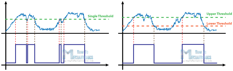
The Schmitt Trigger is a logic input type that provides hysteresis or two different threshold voltage levels for rising and falling edge. This is useful because it can avoid the errors when we have noisy input signals from which we want to get square wave signals.

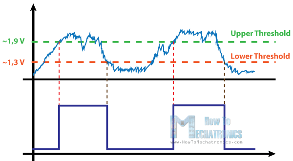
So for example, if we have a noisy input signal like this, that is meant to have 2 pulses, a device that has only one set point, or threshold, could get incorrect input and it could register more than two pulses as shown in this illustration. And if we use the Schmitt Trigger for the same input signal we will get a correct input of two pulses because of the two different thresholds. So that’s the primal function of the Schmitt Trigger, to convert noisy square waves, sine waves or slow edges inputs into clean square waves.
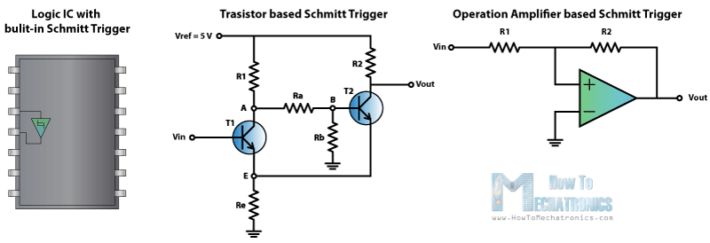
There are many logic ICs that have built-in Schmitt Triggers on their inputs, but also it can be built using transistors or easier using an Operational Amplifier, or comparator and just adding some resistors to it and a positive feedback.
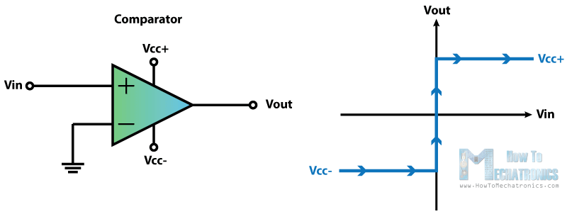
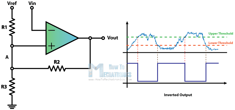
Here we have an op-amp which inverting input is connected to the ground or zero volts and the non-inverting input is connected to a voltage input, VIN. So this is actually a comparator and compares the non-inverting input to the inverting input or in this case the input voltage VIN to 0 V. So when the VIN value is below 0 volts the output of the comparator will be the negative VCC and if the input voltage is above 0 volts the output will be positive VCC.
Now if we add a positive feedback by connecting the output voltage to the non-inverting input with a resistor between them and another resistor between the VIN and the non-inverting input we will get the Schmitt Trigger. Now the output will switch from VCC– to VCC+ when the voltage at the A node will cross 0 volts.
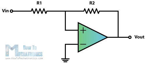
That means that now by adjusting the values of the resistors we can set at what value of the VIN input the switch will occur using the following equations. We get these equations with the following relationships. The current “i” through this line equals VIN – VA divided by R1 as well as VA – VOUT divided by R2. So if we replace the VA with zero, as we need that value for the switch to occur, we will get that final equation. For example if the output is -12 volts and the VIN input is negative and rises, the switch from -12 V to +12 V will occur at 6 volts according to the equation and the values of the resistors and vice versa when the VIN input is high and declines the switch from +12 V to – 12V will occur at -6 volts.

In order to get two different non-symmetrical thresholds, we can use this circuit of an inverting single powered Schmitt Trigger. Here the VREF voltage is the same as the VCC of the op-amp. Now because the VIN input is connected to the inverting input of the op-amp when its values will reach the upper threshold, the output will switch off to 0 volts, and then when its values will decline to the lower threshold, the output will switch on to 5 volts.
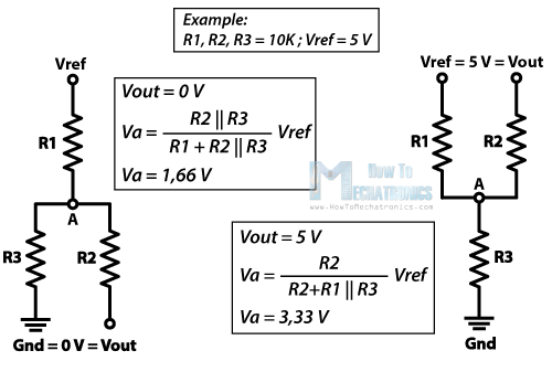
Here’s an example of how we can calculate the thresholds. The VREF and the VCC will be 5 volts and the three resistors will be the same 10k ohms. So what we need to calculate now is the voltage at the A node. In the first case when the output is 0 V our circuit will look like this, a simple voltage divider and the value of the VA will be 1.66 V. This means that the VIN input needs to decline below that value in order the output to switch on to 5 volts. Now with this 5 volts at the output the circuit will look like this. The value of the VA will be 3.33 V. This means that the VIN input needs to rise above that value in order the output to switch off to 0 volts.
The Schmitt Trigger is a logic input type that provides hysteresis or two different threshold voltage levels for rising and falling edge. This is useful because it can avoid the errors when we have noisy input signals from which we want to get square wave signals. The Transistor Schmitt Triger circuit contains two transistors and five resistors. For better explanation I will assign values to the components, and later I will make demonstration and build this circuit on a protoboard to see how it really works.
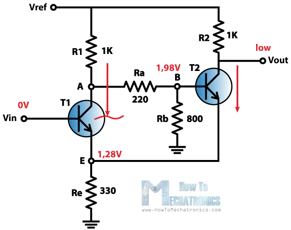
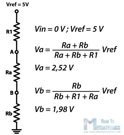
We will start like this. Let’s suppose that the Vin input is 0 V. That means that transistor T1 is cut off and not conducting. On the other hand the Transistor T2 is conducting because we have a voltage of about 1.98 V at the B node as we can consider this part of the circuit as a voltage divider and calculate the voltage using this expressions.
So because the Transistor T2 is conducting the output voltage will be low and the voltage at the emitter will be about 0.7 V lower than the voltage at the base of the transistor, or that’s about 1.28 V.
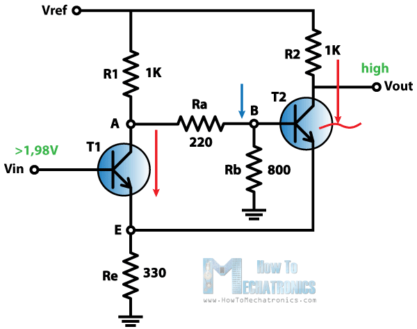
The emitter of the transistor T1 is connected with the emitter of the transistor T2 so they are at the same voltage level of 1.28 V which means that the transistor T1 will turn on when the voltage Vin at its base will be 0.7 V above this value of 1.28 V, or about 1.98 V.
So as we increase the Vin input and we cross this value of 1.98 the transistor T1 will start conducting. This will cause the voltage at the base of the transistor T2 to drop and will cut the transistor off. As the transistor T2 is no longer conducting the output voltage will go high.
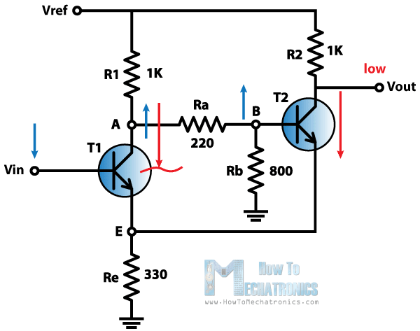
Next, the voltage Vin at the base of the transistor T1 will start declining and it will turn the transistor off when the base voltage will be 0.7 V above the voltage of its emitter. This will happen as the current in the emitter will decline to a point where the transistor will get into forward-active mode. In this mode the collector voltage will increase, which will also increase the voltage at the base of the transistor T2. This will cause small amount of current to flow through the transistor T2 which will further drop the voltage at the emitters and will cause the transistor T1 to turn off. In our case the Vin input needs to drop to about 1.3 V to turn off the transistor T1.
That’s it. Now the cycle repeats over and over again. So we got two thresholds, the high threshold at about 1.9 V and the low threshold at about 1.3 V.
we can volt at node A by use thevenin’s theorem if vref =5 and vin=1.4 and hfe=220
note:
in the previous circuit the current pass the transistor is constant current not affected by remaining of the circuit because that we not use the emitter resistor to calculate Rth


