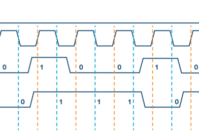
To write code for a new SPI device you need to note a few things:
- What is the maximum SPI speed your device can use? This is controlled by the first parameter in SPISettings. If you are using a chip rated at 15 MHz, use 15000000. Arduino will automatically use the best speed that is equal to or less than the number you use with SPISettings.
- Is data shifted in Most Significant Bit (MSB) or Least Significant Bit (LSB) first? This is controlled by second SPISettings parameter, either MSBFIRST or LSBFIRST. Most SPI chips use MSB first data order.
- Is the data clock idle when high or low? Are samples on the rising or falling edge of clock pulses? These modes are controlled by the third parameter in SPISettings.
SPI.beginTransaction(SPISettings(4000000,MSBFIRST,SPI_MODE0));in arduino uno we have 16 MHZ clock speed so the maximum speed is 16000000 clocks
SPI.setClockDivider(SPI_CLOCK_DIV4)// 16/4 = 4 MHZcalls beginTransaction a second time, the setting are maintained. You should attempt to minimize the time between before you call SPI.endTransaction(), for best compatibility if your program is used together with other libraries which use SPI.
With most SPI devices, after SPI.beginTransaction(), you will write the
slave select pin LOW, call SPI.transfer() any number of times to transfer data, then write the SS pin HIGH, and finally call SPI.endTransaction().
The extended API can use pins 4, 10, and 52 for CS.
Use
You must specify each pin you wish to use as CS for the SPI devices.
It is possible for the Due to automatically handle the chip selection between multiple devices sharing the SPI bus. Each device may have also different attribues such as speed and datamode.
If using multiple devices with different CS pins, you’ll need to declare those pins in setup(). In the following example, there are two devices that share the SPI MISO, MOSI, and SCK pins. One device CS is attached to pin 4, the other to pin 10.
void setup(){
// initialize the bus for a device on pin 4
  SPI.begin(4);
// initialize the bus for a device on pin 10
  SPI.begin(10);
Once a pin has been declared as a CS pin, it’s possible to change its default behaviors as well. For example, if the devices run at different clock speeds, the setup() may look like this :
void setup(){
// initialize the bus for the device on pin 4
  SPI.begin(4);
// Set clock divider on pin 4 to 21
  SPI.setClockDivider(4, 21);
// initialize the bus for the device on pin 10
  SPI.begin(10);
// Set clock divider on pin 10 to 84
  SPI.setClockDivider(10, 84);
}
A single byte transfer to a device on pin 4 could look like this :
void loop(){
  byte response = SPI.transfer(4, 0xFF);
}
In the above, “0xFF” is sent to the SPI device on pin 4 and the data coming from MISO is saved inside the variable response. The chip selection is handled automatically by the SPI controller, the transfer command implies the following:
- Select device by setting pin 4 to LOW
- Send 0xFF through the SPI bus and return the byte received
- Deselect device by setting pin 4 to HIGH
It’s possible to send more than one byte in a transaction by telling the the transfer command to not deselect the SPI device after the transfer :
void loop(){
//transfer 0x0F to the device on pin 10, keep the chip selected
SPI.transfer(10, 0xF0, SPI_CONTINUE);
//transfer 0x00 to the device on pin 10, keep the chip selected
SPI.transfer(10, 0×00, SPI_CONTINUE);
//transfer 0x00 to the device on pin 10, store byte received in response1, keep the chip selected
byte response1 = SPI.transfer(10, 0×00, SPI_CONTINUE);
//transfer 0x00 to the device on pin 10, store byte received in response2, deselect the chip
byte response2 = SPI.transfer(10, 0×00);
}
The parameter SPI_CONTINUE ensures that chip selection is keep active between transfers. On the last transfer SPI_CONTINUE is not specified as it’s the last byte transferred.
See the individual reference pages for setClockDivider(), setDataMode(), transfer(), setBitOrder() for proper syntax when using the extended methods.
NB : once SPI.begin() is called, the declared pin will not be available as a general purpose I/O pin
//arduino uno master
#include<SPI.h>
void setup() {
   digitalWrite(SS, HIGH); // disable Slave Select
   SPI.begin();
   SPI.setClockDivider(SPI_CLOCK_DIV4);//divide the clock by 4
}
void loop() {
   char c;
   digitalWrite(SS, LOW); // enable Slave Select
   for (const char * p = "Hello Mega\r" ; c = *p; p++)
   {
      SPI.transfer(c);
   }
   digitalWrite(SS, HIGH); // disable Slave Select
   delay(2000);
}
//arduino mega slave
#include<SPI.h>
char buff [50];
volatile byte indx;
volatile boolean process;
void setup (void) {
Serial.begin (9600);
pinMode(MISO, OUTPUT); // have to send on master in so it set as output
SPCR |= _BV(SPE); // turn on SPI in slave mode
indx = 0; // buffer empty
process = false;
SPI.attachInterrupt(); // turn on interrupt
}
ISR (SPI_STC_vect) // SPI interrupt routine
{
byte c = SPDR; // read byte from SPI Data Register
if (indx < sizeof buff) {
buff [indx++] = c; // save data in the next index in the array buff
if (c == '\r') //check for the end of the word
process = true;
}
}
void loop (void) {
if (process) {
process = false; //reset the process
Serial.println (buff); //print the array on serial monitor
indx= 0; //reset button to zero
}
}//master esp32 arduino
#include <Arduino.h>
#include <SPI.h>
SPIClass spi;
void setup() {
Serial.begin(9600);
spi=SPIClass(VSPI);
spi.begin();
pinMode(5,OUTPUT);
digitalWrite(5,HIGH);
}
void loop() {
delay(5000);
digitalWrite(5,LOW);
spi.beginTransaction(SPISettings(4000000,MSBFIRST,SPI_MODE0));
spi.transfer(99);
digitalWrite(5,HIGH);
spi.endTransaction();
}

