

SR Latch

and it’s symbol is

- The enable input on a multivibrator must be activated for either S or R inputs to have any effect on the output state.
- This enable input is sometimes labeled “E”, and other times as “EN”.


D Latch
- A D latch is like an S-R latch with only one input: the “D” input. Activating the D input sets the circuit, and de-activating the D input resets the circuit. Of course, this is only if the enable input (E) is activated as well. Otherwise, the output(s) will be latched, unresponsive to the state of the D input.
- D latches can be used as 1-bit memory circuits, storing either a “high” or a “low” state when disabled, and “reading” new data from the D input when enabled.


Edge-triggered Latches: Flip-Flops
compare timing diagrams for a normal D latch versus one that is edge-triggered:

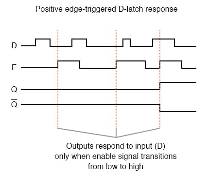
Implementing this timing function with semiconductor components is actually quite easy, as it exploits the inherent time delay within every logic gate (known as propagation delay). What we do is take an input signal and split it up two ways, then place a gate or a series of gates in one of those signal paths just to delay it a bit, then have both the original signal and its delayed counterpart enter into a two-input gate that outputs a high signal for the brief moment of time that the delayed signal has not yet caught up to the low-to-high change in the non-delayed signal. An example circuit for producing a clock pulse on a low-to-high input signal transition is shown here:

This circuit may be converted into a negative-edge pulse detector circuit with only a change of the final gate from AND to NOR:

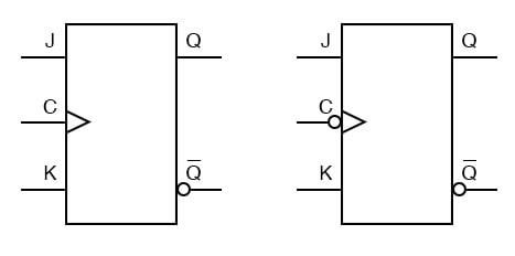
The block symbols for flip-flops are slightly different from that of their respective latch counterparts:

The triangle symbol next to the clock inputs tells us that these are edge-triggered devices, and consequently that these are flip-flops rather than latches. The symbols above are positive edge-triggered: that is, they “clock” on the rising edge (low-to-high transition) of the clock signal. Negative edge-triggered devices are symbolized with a bubble on the clock input line:

- A flip-flop is a latch circuit with a “pulse detector” circuit connected to the enable (E) input, so that it is enabled only for a brief moment on either the rising or falling edge of a clock pulse.
- Pulse detector circuits may be made from time-delay relays for ladder logic applications, or from semiconductor gates (exploiting the phenomenon of propagation delay).
J-K Flip-Flop
Another variation on a theme of bistable multivibrators is the J-K flip-flop. Essentially, this is a modified version of an S-R flip-flop with no “invalid” or “illegal” output state. Look closely at the following diagram to see how this is accomplished:
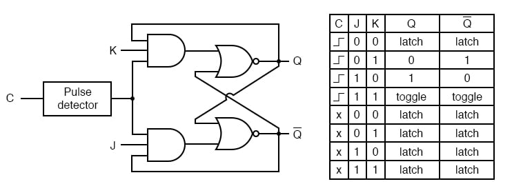
- A J-K flip-flop is nothing more than an S-R flip-flop with an added layer of feedback. This feedback selectively enables one of the two set/reset inputs so that they cannot both carry an active signal to the multivibrator circuit, thus eliminating the invalid condition.
- When both J and K inputs are activated, and the clock input is pulsed, the outputs (Q and not-Q) will swap states. That is, the circuit will toggle from a set state to a reset state or vice versa.
Asynchronous Flip-Flop Inputs
The normal data inputs to a flip flop (D, S and R, or J and K) are referred to as synchronous inputs because they have an effect on the outputs (Q and not-Q) only in step, or in sync, with the clock signal transitions.
These extra inputs that I now bring to your attention are called asynchronous because they can set or reset the flip-flop regardless of the status of the clock signal. Typically, they’re called preset and clear:
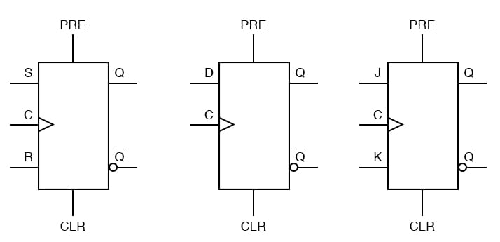
When the preset input is activated, the flip-flop will be set (Q=1, not-Q=0) regardless of any of the synchronous inputs or the clock. When the clear input is activated, the flip-flop will be reset (Q=0, not-Q=1), regardless of any of the synchronous inputs or the clock.
So, what happens if both preset and clear inputs are activated? Surprise, surprise: we get an invalid state on the output, where Q and not-Q go to the same state, the same as our old friend, the S-R latch!
- Asynchronous inputs on a flip-flop have control over the outputs (Q and not-Q) regardless of clock input status.
- These inputs are called the preset (PRE) and clear (CLR). The preset input drives the flip-flop to a set state while the clear input drives it to a reset state.
- It is possible to drive the outputs of a J-K flip-flop to an invalid condition using the asynchronous inputs, because all feedback within the multivibrator circuit is overridden.