
Diod Transistors
Transistor as a Zener

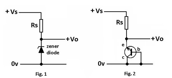
Zener diodes connected as shown in Fig. 1 are carefully doped at manufacture such that they break down when a critical reverse bias voltage is applied and allows current to flow. The current is limited by the power ratings of the particular device employed.
Zeners are used to provide a voltage reference and any transistor can be employed to do the same job if connected as shown in Fig. 2.
Different transistors will produce different zener voltages and a series of tests can be done to establish what the typical zener voltage is for that device.
A suitable setup could be employed as shown below.

A BC548B gives a zener voltage Vz = 8.2V
A BC549B gives a zener voltage Vz = 10.8V
A BC547B gives a zener voltage Vz = 9.1V
A BC184 gives a zener voltage Vz = 8.2V
Using the Configuration in Practice

The above circuit Fig 4 could form the basis of a low power regulated power supply.
Vbe Multiplayer
Variable Reference Voltage Circuit

Fig. 5 shows a way of adjusting the voltage Vz to suit by adjusting the resistor values of R1 and R2.
Vz = Vbe((R1 + R2)/R2)
Better regulation can be achieved with a darlington configuration as shown below where it is used in a simple regulated supply, but now the voltage Vz becomes:-
Vz = 2Vbe((R1 + R2)/R2)
and the regulated output voltage becomes:-
Vo = Vz – Vbe

Other more circuits


